Beginner Arduino Project: Turn ON/OFF LED using Push Button
Have you ever wanted to use your Arduino to play "light on, light off"? Well, all you need is an LED and a push button to do that! As you press a button, picture your LED glowing like it's saying "hello." Are you ready to discover this magical interactive experience?
So how does this work? When you click the button, the Arduino gets the signal to turn on the LED! Your button appears to be sending a hidden message, causing the LED to flicker. Would you want to learn how to do this fun project? Now let's get started!
Overview of this Experiment
Light is released when power flows through a small, energy-efficient light source called an LED (Light Emitting Diode). Because LEDs come in a range of colours and sizes, they are versatile for electronics applications. They are widely used in indicators, displays, and illumination. Their extended lifespan and low power consumption make them perfect for do-it-yourself applications and embedded devices.A push button is a simple switch that controls an electrical circuit when it is depressed. It has the ability to create or sever the connection, which would result in a project action. Push buttons are commonly employed in electronics for human inputs such as starting or stopping activities. They are essential in interactive systems because they allow users to control equipment with a single push.

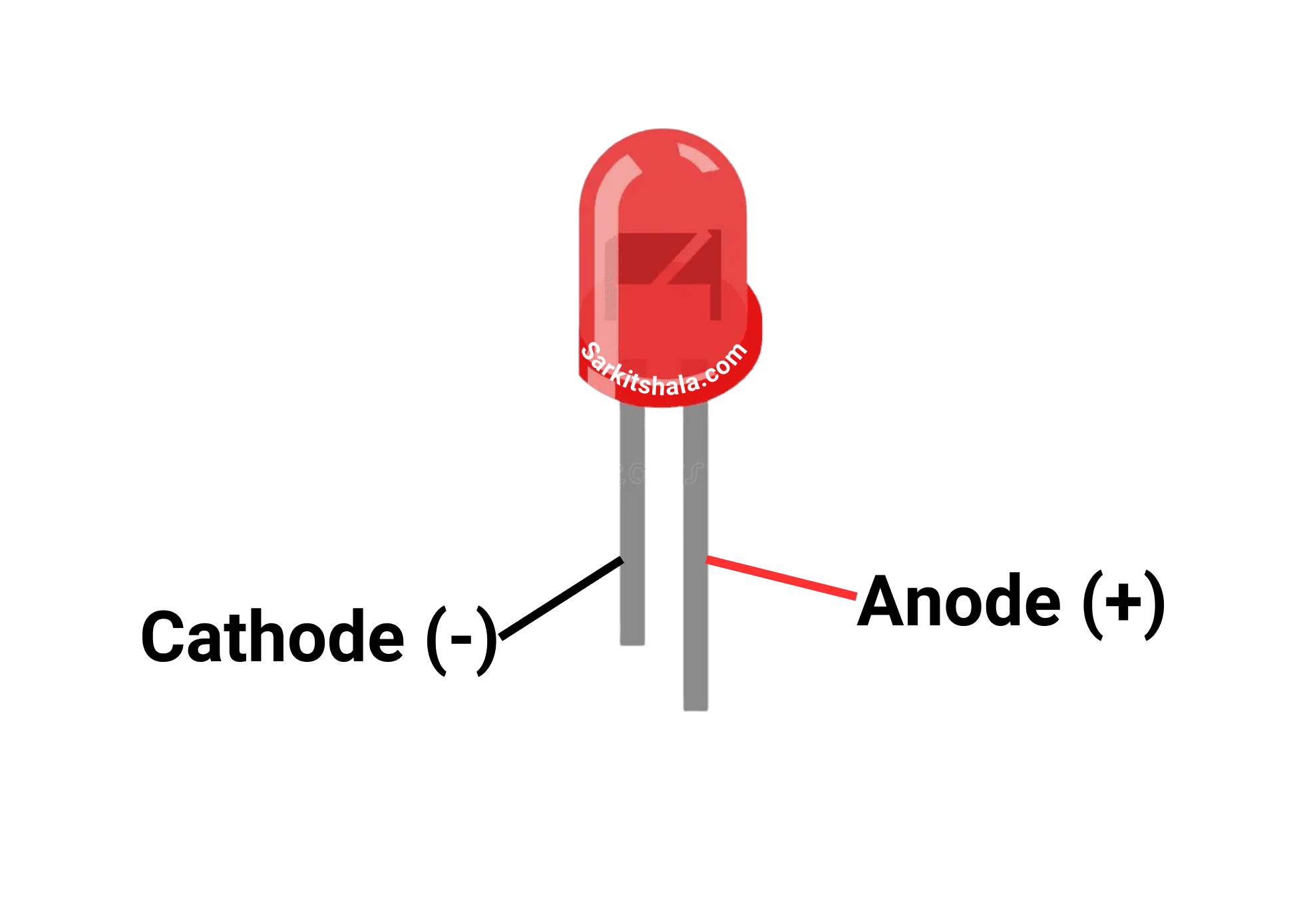
Pin Diagram of LED
Circuit Diagram

Steps
1. Connect LED with the Arduino Board.
2. Connect the Push Button with Arduino Board.
3. Connect the B-Type cable with the microcontroller.
4. Install and write code in Arduino IDE.
5. Compile and upload the code in Arduino .
Code
1
2#define LED_PIN 13     // Pin where the LED is connected
3#define BUTTON_PIN 2   // Pin where the push button is connected
4
5void setup() {
6  // Initialize the LED pin as an output:
7  pinMode(LED_PIN, OUTPUT);
8
9  // Initialize the BUTTON_PIN as an input with an internal pull-up resistor:
10  pinMode(BUTTON_PIN, INPUT_PULLUP);
11}
12
13void loop() {
14  // Read the state of the push button
15  int buttonState = digitalRead(BUTTON_PIN);
16
17  // Check if the button is pressed
18  if (buttonState == LOW) {  // Button pressed (since we are using INPUT_PULLUP)
19    digitalWrite(LED_PIN, HIGH);  // Turn the LED on
20  } else {
21    digitalWrite(LED_PIN, LOW);   // Turn the LED off
22  }
23}
24
25