Arduino LDR Interface: Light Sensor Wiring & Code Guide

LDR (Light Dependent Resistor)
An LDR (Light Dependent Resistor) is a light-sensitive device whose resistance decreases as the light intensity increases. It is commonly used to detect light levels in applications such as automatic lighting systems, light meters, and security systems. By connecting an LDR to an Arduino's analog input, you can measure light intensity and trigger specific actions based on the light levels.
How Does an LDR Work
Explanation of Code
The code reads the analog input from the LDR using the analogRead() function. This value (0-1023) corresponds to the voltage drop across the LDR, which changes with light intensity. By comparing the reading to a predefined threshold, the Arduino can decide whether to activate devices like LEDs or relays. For example, if the light level falls below 500, the Arduino turns on an LED, simulating an automatic light system. The Serial Monitor outputs real-time light intensity readings, which can be calibrated by adjusting the resistor value or modifying the threshold in the code.
Applications of LDRs
Arrangement
1. LDR Pin 1 (Connected to 5V)
2. LDR Pin 2 (Connected to Analog Pin with a Resistor to GND)
Types of LDRs
Cadmium Sulfide (CdS) LDR
- Sensitive to visible light between 400-700 nm.
- Widely used for general light detection applications.
- Affordable and ideal for consumer electronics.
InGaAs Photocell LDR
- Operates in the near-infrared spectrum (800-2600 nm).
- Used in specialized applications like optical communication.
- More accurate but expensive compared to CdS LDRs.
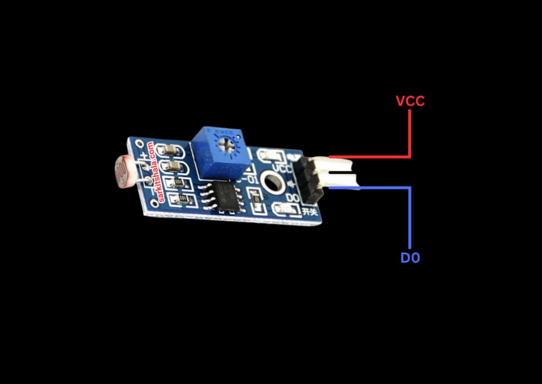
Pin Configuration of LDR
LDR with Voltage Divider
- VCC: Connect one terminal of the LDR to 5V on Arduino.
- GND: Connect a resistor (e.g., 10kΩ) from the other LDR terminal to Arduino ground (GND).
- Analog Pin: Connect the junction of the LDR and resistor to an analog input pin on Arduino.
- This configuration forms a voltage divider circuit to measure light intensity.
LDR with Digital Input
- VCC: Connect one terminal of the LDR to 5V on Arduino.
- GND: Connect the other terminal to GND through a pull-down resistor (e.g., 10kΩ).
- Digital Pin: Connect the junction of the LDR and resistor to a digital input pin.
- Use this setup to detect light presence (HIGH/LOW) instead of precise intensity.
Components Required
- Arduino Uno (or any compatible board)
- LDR (Light Dependent Resistor)
- 10kΩ Resistor (for voltage divider)
- Connecting Wires
- Breadboard (optional)
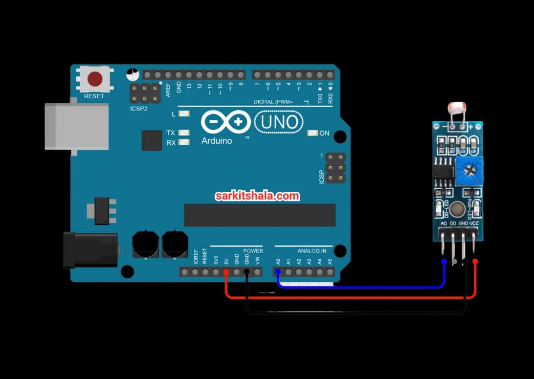
Circuit Connections
LDR with Arduino (Basic Setup)
- Connect one terminal of the LDR to Arduino 5V.
- Connect the other terminal of the LDR to Arduino analog pin A0.
- Attach a 10kΩ resistor between the LDR's second terminal and GND.
- This forms a voltage divider to measure light intensity.
- Read the analog value from A0 to detect light levels.
LDR with Arduino (Digital Detection Setup)
- Connect one terminal of the LDR to Arduino digital pin 7.
- Connect the other terminal of the LDR to 5V.
- Place a 10kΩ resistor between the digital pin and GND (pull-down resistor).
- When light falls on the LDR, the pin reads LOW, otherwise HIGH.
LDR with Arduino (Multiple Sensor Setup)
- Connect multiple LDRs to different analog pins (e.g., A0, A1, A2).
- Each LDR should form a voltage divider using a 10kΩ resistor to GND.
- Read light intensity from each pin and process them in the Arduino code.
- Ensure each LDR circuit is identical for accurate measurement.
LDR with Arduino (Low-Light Detection)
- Use a high-value resistor (e.g., 47kΩ) instead of 10kΩ for low-light conditions.
- Connect the LDR and resistor in a voltage divider configuration.
- Monitor the analog pin for increased sensitivity to low light.
- Adjust the resistor value based on the desired sensitivity.
Algorithm
Define the Pins
- Identify the analog input pin for the LDR (e.g., A0).
- Connect the LDR and resistor to form a voltage divider.
Initialize the Arduino
- Set up the serial communication in the setup() function.
- Configure the analog pin to read LDR values.
Read Light Intensity
- Use analogRead() to capture the voltage from the LDR.
- Map the analog value (0-1023) to a light intensity range.
- Display the light intensity on the Serial Monitor.
Trigger Actions
- Set a light threshold value (e.g., 500 for low light).
- Turn on an LED or activate a relay when the light is below the threshold.
Repeat the Process
- Continuously monitor light intensity and respond to changes.
- Adjust thresholds for specific applications.
Arduino Code
1// Arduino LDR Interface: Light Sensor Wiring & Code Guide
2// This code reads light intensity using an LDR and prints it to the Serial Monitor
3
4// Connect one end of the LDR to 5V
5// Connect the other end to analog pin A0 AND to GND via a 10kΩ resistor (voltage divider)
6
7// Define the analog pin connected to the LDR
8#define LDR_PIN A0
9
10void setup() {
11  // Initialize serial communication to display readings on Serial Monitor
12  Serial.begin(9600);
13}
14
15void loop() {
16  // Read the analog value from the LDR
17  int ldrValue = analogRead(LDR_PIN);
18
19  // Print the light intensity value (range: 0 to 1023)
20  Serial.print("LDR Value: ");
21  Serial.println(ldrValue);
22
23  // You can use this value to trigger actions
24  // For example, if it's too dark, turn on a light
25  /*
26  if (ldrValue < 300) {
27    // It's dark
28    Serial.println("It's dark - you can turn on an LED here.");
29  }
30  */
31
32  delay(500); // Wait half a second before taking the next reading
33}
34
Applications
- Automatic Street Lights
- Light-Controlled Alarms
- Solar Tracking Systems
- Photographic Light Meters
- Home Automation
- Security Systems
Conclusion
Interfacing an LDR with Arduino enables light-based automation, such as controlling devices in response to changing light levels. By forming a voltage divider and reading analog inputs, the Arduino detects varying light intensities. This system is useful for applications like automatic lighting, solar tracking, and security. With the ability to adjust sensitivity through resistor selection and threshold settings, the Arduino-LDR combination offers a versatile solution for light-dependent projects.