Smart LED Traffic Light System

Written By - Sakshi Singh
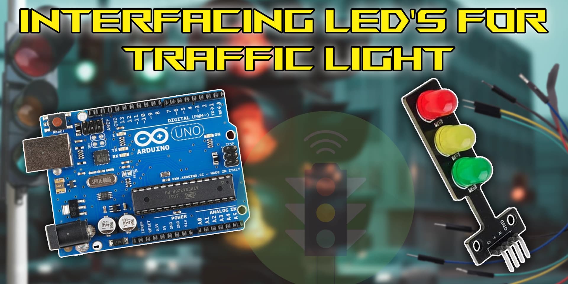
Building a traffic signal system by integrating LEDs is an entertaining and instructive project that illustrates practical traffic control. You can learn how to manipulate signals, timing, and control logic for effective traffic management systems by simulating red, yellow, and green lights using LEDs connected to a microcontroller.
Using LEDs to create a traffic light system facilitates the exploration of electronics and programming principles. You may control light sequences, modify timings, and replicate actual traffic signals by connecting LEDs to a microcontroller. This interactive project is ideal for studying automation and smart city ideas since it improves comprehension of signal control.
An Overview of Arduino and LED
In this project, a microcontroller and LEDs are used to create a small traffic light system. Through preprogrammed sequences, the LEDs will govern traffic flow by representing red, yellow, and green lights. It provides practical experience with signal management, timing, and fundamental electronics automation ideas by mimicking real-world traffic control.The system employs a microcontroller with pre-programmed logic to regulate LED signals. It can be modified for smart traffic systems by adding sensors or timers for improved functionality. This project is perfect for learning the fundamentals of coding, hardware control, and the ideas underlying contemporary traffic management solutions.

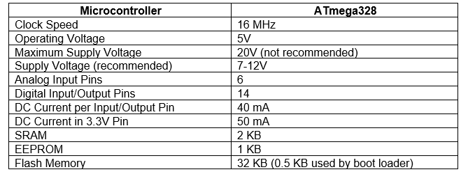
Pin Diagram

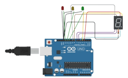
Circuit Diagram

Steps
1. Place the Arduino Uno on the breadboard.
2. Connect the ground (GND) pin of the Arduino to the negative rail (-) on the breadboard.
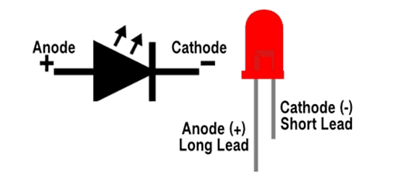
3. Grab your red LED – Connect its long leg (the anode) to digital pin 2 on your Arduino, but don’t forget the 220-ohm resistor! Think of it as the LED’s personal bodyguard, keeping it safe from an electrical overload meltdown!
4. Hook up the yellow LED’s long leg (anode) to pin 3 with a 220-ohm resistor—safety first, no LED barbeque!
5. Using a 220-ohm resistor, connect the green LED's long leg (anode) to digital pin 4 on the Arduino.
6. Attach the shorter leg (cathode) of each LED to the ground rail (-) on the breadboard.
Code
1
2int A=3;
3int B=4;
4int C=5;
5int D=6;
6int E=7;
7int F=8;
8int G=9;
9int X=10;
10int Y=11;
11int Z=12;
12void setup()
13 {
14          pinMode(A, OUTPUT);
15          pinMode(B, OUTPUT);
16          pinMode(C, OUTPUT);
17          pinMode(D, OUTPUT);
18          pinMode(E, OUTPUT);
19          pinMode(F, OUTPUT);
20          pinMode(G, OUTPUT);
21          pinMode(X, OUTPUT);
22          pinMode(Y, OUTPUT);
23          pinMode(Z, OUTPUT);
24          }
25void loop()
26{
27
28          digitalWrite(A, HIGH);
29          digitalWrite(B ,HIGH);
30          digitalWrite(C, HIGH);
31          digitalWrite(D, HIGH);
32          digitalWrite(E, HIGH);
33          digitalWrite(F, HIGH);
34          digitalWrite(G, LOW);
35          delay(1000);
36          digitalWrite(A, LOW);
37           digitalWrite(B ,HIGH);
38           digitalWrite(C, HIGH);
39           digitalWrite(D, LOW);
40           digitalWrite(E, LOW);
41           digitalWrite(F, LOW);
42           digitalWrite(G, LOW);
43           delay(1000);
44           digitalWrite(A, HIGH);
45           digitalWrite(B ,HIGH);
46           digitalWrite(C, LOW);
47           digitalWrite(D, HIGH);
48           digitalWrite(E, HIGH);
49           digitalWrite(F, LOW);
50           digitalWrite(G, HIGH);
51           delay(1000);
52           digitalWrite(A, HIGH);
53           digitalWrite(B ,HIGH);
54           digitalWrite(C, HIGH);
55           digitalWrite(D, HIGH);
56           digitalWrite(E, LOW);
57           digitalWrite(F, LOW);
58           digitalWrite(G, HIGH);
59           delay(1000);
60           digitalWrite(A, LOW);
61           digitalWrite(B ,HIGH);
62           digitalWrite(C, HIGH);
63           digitalWrite(D, LOW);
64           digitalWrite(E, LOW);
65           digitalWrite(F, HIGH);
66           digitalWrite(G,HIGH);
67           delay(1000);
68           digitalWrite(A, HIGH);
69           digitalWrite(B ,LOW);
70           digitalWrite(C, HIGH);
71           digitalWrite(D, HIGH);
72           digitalWrite(E, LOW);
73           digitalWrite(F, HIGH);
74           digitalWrite(G, HIGH);
75           delay(1000);
76           digitalWrite(A, LOW);
77           digitalWrite(B ,LOW);
78           digitalWrite(C, HIGH);
79           digitalWrite(D, HIGH);
80           digitalWrite(E, HIGH);
81           digitalWrite(F, HIGH);
82           digitalWrite(G, HIGH);
83           delay(1000);
84           digitalWrite(A, HIGH);
85           digitalWrite(B ,HIGH);
86           digitalWrite(C, HIGH);
87           digitalWrite(D, LOW);
88           digitalWrite(E, LOW);
89           digitalWrite(F, LOW);
90           digitalWrite(G, LOW);
91           delay(1000);
92           digitalWrite(A, HIGH);
93           digitalWrite(B ,HIGH);
94           digitalWrite(C, HIGH);
95           digitalWrite(D, HIGH);
96           digitalWrite(E, HIGH);
97           digitalWrite(F, HIGH);
98           digitalWrite(G, HIGH);
99           delay(1000);
100           digitalWrite(A, HIGH);
101           digitalWrite(B ,HIGH);
102           digitalWrite(C, HIGH);
103           digitalWrite(D, LOW);
104           digitalWrite(E, LOW);
105           digitalWrite(F, HIGH);
106           digitalWrite(G, HIGH);
107           delay(1000);
108
109           }
110