Interfacing Arduino with Joystick Module
Joystick Module
A joystick module is an input device that sends analog signals representing the position of the joystick's X and Y axes. It consists of two potentiometers and can be used for controlling movement in games, robotics, or other projects.
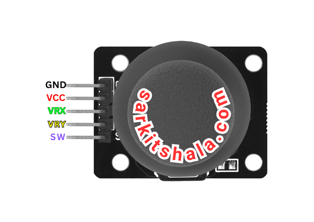
Joystick Module Pinout
The joystick typically has five pins: VCC, GND, VRx (X-axis), VRy (Y-axis), and SW (Switch). These pins are used for supplying power, receiving analog signals, and detecting button presses.
Wiring the Joystick to Arduino
To begin interfacing the joystick with Arduino, you need to connect the VCC, GND, and the X/Y axis analog pins to the appropriate Arduino pins. If using a joystick button, you also connect it to a digital pin.
Types of Joystick Modules
Analog Joystick
- X-axis: Outputs an analog signal representing the horizontal movement.
- Y-axis: Outputs an analog signal representing the vertical movement.
- SW (Switch): A button press can be detected as a digital signal.
Digital Joystick
- The joystick button sends a digital signal when pressed.
- Movement is detected as a high or low digital state.
Pin Configuration of Joystick Module
Analog Joystick
- VCC: Connect to +5V on Arduino.
- GND: Connect to GND on Arduino.
- VRx: Connect to an analog input pin (e.g., A0).
- VRy: Connect to an analog input pin (e.g., A1).
- SW: Connect to a digital input pin (e.g., D2).
Digital Joystick
- VCC: Connect to +5V on Arduino.
- GND: Connect to GND on Arduino.
- X-axis: Connect to digital input pins (e.g., D2, D3, D4, D5).
- Y-axis: Connect to digital input pins (e.g., D6, D7).
Algorithm
Initialize Components
- Connect the VCC and GND pins of the joystick module to +5V and GND on the Arduino.
- Connect the VRx and VRy pins of the joystick to analog input pins (A0 and A1).
- Connect the SW pin to a digital input pin (D2).
Write the Code
- Set the analog input pins for VRx and VRy as INPUT.
- Set the digital input pin for the switch as INPUT_PULLUP.
- Read the analog values from VRx and VRy to control movement or behavior.
Display Values or Control Motor
- Use the analog values to control the movement of a servo or motor.
- Print the joystick values to the serial monitor for debugging.
Test the Project
- Upload the code to the Arduino.
- Test the joystick's movement and button press functionality.
Arduino Code
1// Arduino Joystick Module: Wiring & Code Guide
2// This code reads analog values from a joystick and prints the X and Y positions on the Serial Monitor
3
4const int VRx = A0;  // Joystick X-axis pin
5const int VRy = A1;  // Joystick Y-axis pin
6const int SW = 2;    // Joystick switch pin (button press)
7
8void setup() {
9  Serial.begin(9600);         // Start serial communication
10  pinMode(SW, INPUT_PULLUP);  // Set switch pin as input with pull-up
11  Serial.println(\"Joystick Module Interface Ready\");
12}
13
14void loop() {
15  int xPosition = analogRead(VRx);  // Read X-axis
16  int yPosition = analogRead(VRy);  // Read Y-axis
17  int buttonState = digitalRead(SW); // Read button press
18
19  Serial.print(\"X: \");
20  Serial.print(xPosition);
21  Serial.print(\" | Y: \");
22  Serial.print(yPosition);
23  Serial.print(\" | Button: \");
24  Serial.println(buttonState == LOW ? \"Pressed\" : \"Released\");
25
26  delay(300);  // Delay for readability
27}
Applications
- Video game controllers
- Robotics (movement control)
- RC Cars and planes
- Drone controls
- Motorized vehicles (e.g., electric wheelchairs)
Conclusion
Interfacing a joystick module with Arduino is an easy and fun way to add interactive control to your projects. Whether for a robot or a video game controller, joystick modules provide smooth and precise input control. With just a few simple steps and some coding, you can integrate this useful component into your next DIY project.