Ultimate Guide to Gear Motor Control with Arduino

In general, a motor driver module such as an H-bridge or a motor shield is used to connect a one-gear motor to Arduino. After you've connected the driver module to the Arduino, attach the motor. Determine the motor's power requirements first, and then choose a driver that matches the motor's voltage and current. To control the speed and direction of the motor, send signals to the motor driver using Arduino.
To initialise the motor pins, specify the direction, and alter the speed via PWM (Pulse Width Modulation), you must enter code in the Arduino IDE. PWM allows you to control the speed of a motor by adjusting the voltage it receives. Check that the motor and Arduino are receiving the appropriate quantity of energy. Make sure your setting is correct.
Overview of this Experiment
A gear motor is a tiny mechanical device that combines a gear system and an electric motor. Its goal is to provide torque output that may be applied in a number of ways. While the electric motor converts electrical energy into mechanical energy, the gear system increases torque and changes rotational speed. Among the several varieties of gear motors that are available are spur, helical, worm, and planetary gears; each is suitable for a certain torque and speed requirement. They are extensively utilised in robotics, industrial and automotive machinery, and household appliances where precise torque and speed control are essential. Because of their compact size, high efficiency, and adaptability, which enable them to perform better and more smoothly on a range of tasks, they are a crucial part of many mechanical systems.The Arduino Uno is a popular microcontroller board among professionals, educators, and enthusiasts. It has an ATmega328P CPU with a 16 MHz clock, 2 KB of SRAM for variables, and 32 KB of flash memory for code. With 14 digital input/output ports, 6 analogue inputs, and a variety of communication interfaces including SPI, I2C, and UART, the Uno provides versatile connections for integrating with sensors, actuators, and other electrical components. Because of its simplicity and ease of use, it's an excellent platform for beginners learning electronics and programming. The Uno may be programmed using the Arduino Integrated Development Environment (IDE), which offers an intuitive interface for writing, creating, and uploading code.

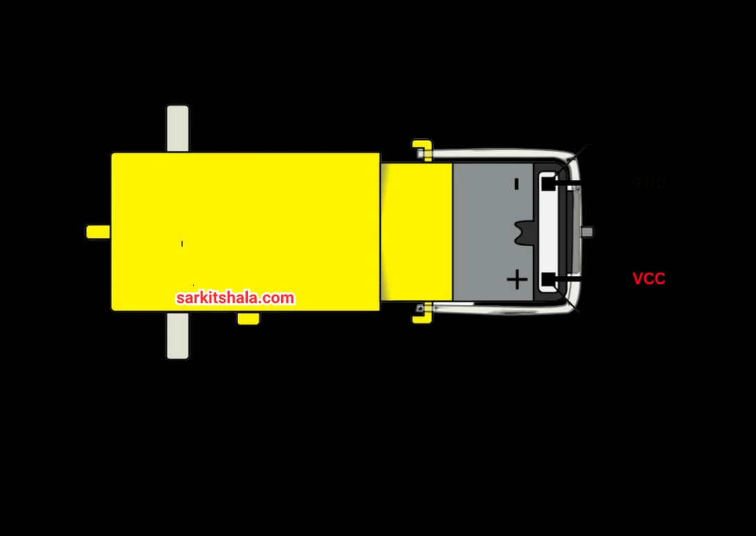
Pin Diagram of Gear Motor
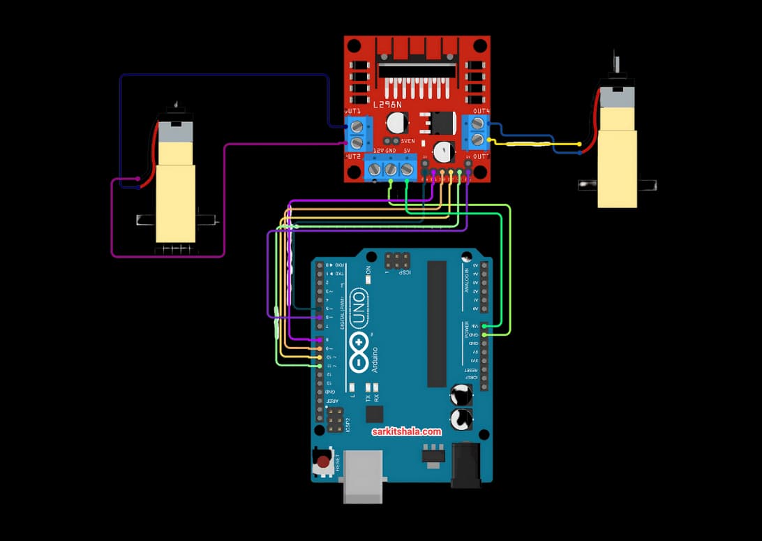
Circuit Diagram
Steps
1. Attach the two wires of the DC motor to the motor driver's OUT1 and OUT2 terminals.
2. Attach a 6V–12V external battery to the driver's VCC and GND, making sure the GND is linked to the Arduino GND as well.
3. To control direction, connect the Arduino digital pins (such as D8 and D9) to the logic pins (IN1 and IN2) of the driver.
4. To enable speed adjustment, connect the driver's ENA (Enable) pin to an Arduino PWM pin (such as D10).
5. Use digitalWrite() for direction and analogWrite() for speed control (0 to 255) when uploading the Arduino program.
6. Compile and upload the code in Arduino.
Code
1
2
3const int dirPin1 = 13;
4void setup()
5{
6       pinMode(dirPin1, OUTPUT);
7}
8void loop()
9{
10         digitalWrite(dirPin1, HIGH);
11         digitalWrite(dirPin1, LOW);
12}
13
14