Best Arduino Projects, Pin Guides & Step-by-Step Tutorials for Beginners

What is Arduino? Understand its Features, Boards & Benefits
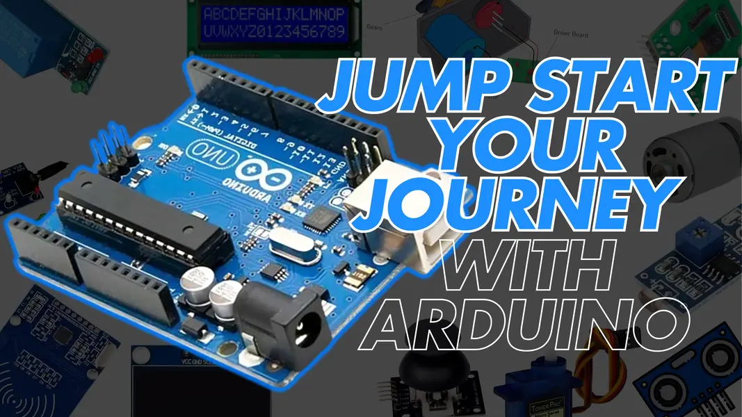
Arduino is an open-source electronics platform based on easy-to-use hardware and software. It allows users to read data from sensors and control actuators like motors, LEDs, and displays. It is widely used in DIY projects, IoT systems, robotics, and educational kits.
How to Use Digital, Analog, and PWM Pins
Understanding the types of pins is crucial to building Arduino projects:
1. Digital Pins
These are used to read/write HIGH or LOW signals. You can connect LEDs, switches, relays, etc. Use `pinMode()`, `digitalWrite()`, and `digitalRead()` functions.
2. Analog Pins
Analog pins (A0-A5) are used with analog sensors like LDR, temperature sensors, etc. They use `analogRead()` to measure voltages.
3. Power Pins
These provide 3.3V or 5V power and GND to components like sensors and modules. Vin is used for supplying power from external sources.
4. PWM Pins
Pins marked with `~` can output PWM signals. Used in applications like dimming LEDs, controlling speed of DC motors and angle of servos.
5. Communication Pins
For communication between boards or modules: - TX/RX: Serial - SDA/SCL: I2C - MOSI/MISO/SCK: SPI
Steps to Get Started with Arduino
- Download and install Arduino IDE.
- Connect your Arduino board using USB cable.
- Select your board and COM port from Tools menu.
- Write a simple sketch like Blink.
- Click Upload button to flash code.
- Observe output (like LED blinking).
Conclusion
Arduino makes learning electronics fun and accessible. With just a few components and a USB cable, you can start building real-world projects and gain valuable hardware and programming skills.
Frequently Asked Questions about Arduino
1. What is Arduino used for?
Arduino is widely used for DIY electronics, IoT projects, robotics, and STEM education. It helps you interact with the physical world using sensors and actuators.
2. Is Arduino good for beginners?
Yes! Arduino has a simple interface, a large supportive community, and plenty of tutorials. It's ideal for beginners who want to learn electronics and coding.
3. Which Arduino board is best to start with?
The Arduino Uno is the most recommended board for beginners due to its reliability, community support, and simplicity.