Interfacing Keypad with Arduino

Keypad Module
A keypad is a user input device consisting of rows and columns of buttons. Each button press generates a unique combination of row and column signals, which the Arduino reads to identify the key. It is commonly used in security systems, menu navigation, and other interactive applications.
How Does a Keypad Work
Explanation of Code
The code reads input from a keypad matrix using the Keypad library. It continuously scans the rows and columns to detect which button is pressed. Based on the key press, specific actions like password validation or menu navigation are performed. This allows building secure input systems efficiently.
Applications of Keypad Modules
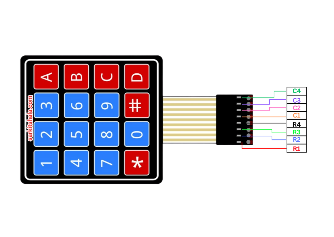
Arrangement
1: ROW1
2: ROW2
3: ROW3
4: ROW4
5: COL1
6: COL2
7: COL3
8: COL4 (optional)
Types of Keypads
4x3 Keypad
- 4 rows and 3 columns (12 buttons total).
- Typically used for basic numeric inputs (0-9, *, #).
4x4 Keypad
- 4 rows and 4 columns (16 buttons total).
- Suitable for advanced input like alphanumeric menus.
Pin Configuration of Keypad
4x3 Keypad Pin Configuration
- Pins 1-4: Connect to Arduino digital pins (row pins).
- Pins 5-7: Connect to Arduino digital pins (column pins).
4x4 Keypad Pin Configuration
- Pins 1-4: Connect to row pins on Arduino.
- Pins 5-8: Connect to column pins on Arduino.
Components Required
- Arduino Uno (or compatible board)
- 4x3 or 4x4 Keypad Module
- Jumper Wires
- Breadboard (optional)
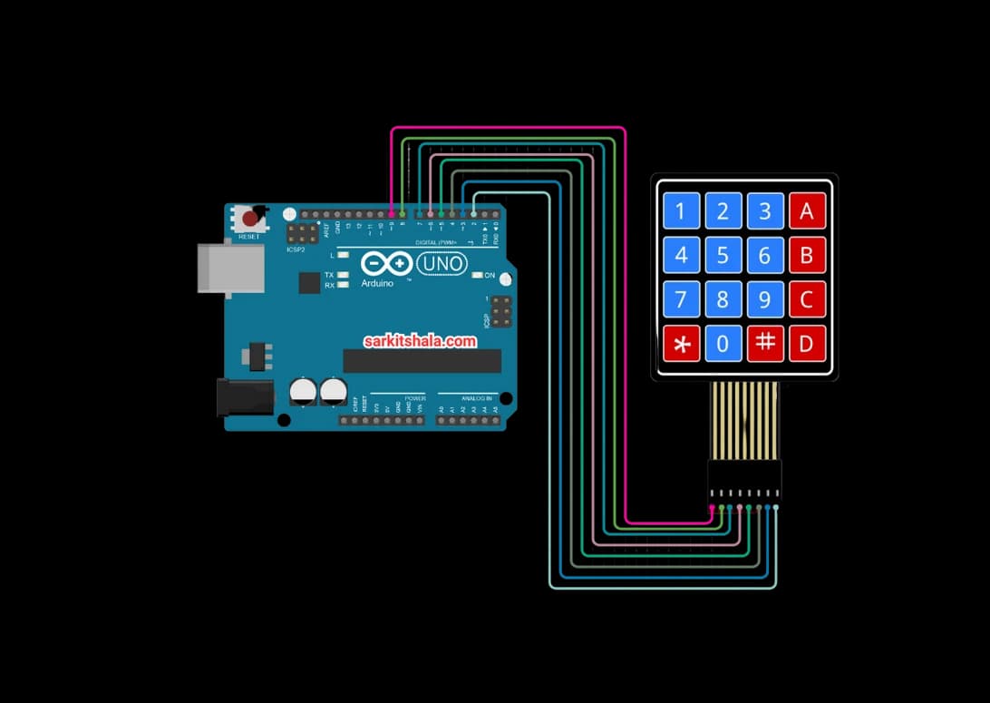
Circuit Connections
4x3 Keypad to Arduino
- Connect ROW1 to Arduino digital pin 9.
- Connect ROW2 to Arduino digital pin 8.
- Connect ROW3 to Arduino digital pin 7.
- Connect ROW4 to Arduino digital pin 6.
- Connect COL1 to Arduino digital pin 5.
- Connect COL2 to Arduino digital pin 4.
- Connect COL3 to Arduino digital pin 3.
4x4 Keypad to Arduino
- Connect ROW1 to pin 9, ROW2 to pin 8, ROW3 to pin 7, ROW4 to pin 6.
- Connect COL1 to pin 5, COL2 to pin 4, COL3 to pin 3, COL4 to pin 2.
Algorithm
Define the Pins
- Assign the keypad rows and columns to Arduino digital pins.
Initialize the Arduino
- Include the <Keypad.h> library.
- Initialize the keypad matrix in the setup() function.
Read Keypad Input
- Continuously check for key presses using the getKey() function.
- Identify the pressed key and store it.
Process the Input
- Perform actions based on key presses (e.g., unlock a door).
- Implement logic for multi-digit inputs (e.g., password entry).
Repeat the Process
- Continuously scan the keypad and update the output accordingly.
Arduino Code
1// Arduino Keypad Interface: User Input System
2// This code reads key presses from a 4x4 matrix keypad and displays them on the Serial Monitor
3
4#include <Keypad.h>  // Include the keypad library
5
6const byte ROWS = 4; // Four rows
7const byte COLS = 4; // Four columns (set to 3 for 4x3 keypad)
8
9// Define the symbols on the keys of the keypad
10char keys[ROWS][COLS] = {
11  {'1','2','3','A'},
12  {'4','5','6','B'},
13  {'7','8','9','C'},
14  {'*','0','#','D'}
15};
16
17// Connect keypad ROW0, ROW1, ROW2 and ROW3 to these Arduino pins
18byte rowPins[ROWS] = {9, 8, 7, 6};
19
20// Connect keypad COL0, COL1, COL2 and COL3 to these Arduino pins
21byte colPins[COLS] = {5, 4, 3, 2};
22
23// Create the Keypad object
24Keypad keypad = Keypad(makeKeymap(keys), rowPins, colPins, ROWS, COLS);
25
26void setup() {
27  Serial.begin(9600); // Start serial communication
28  Serial.println(\"Keypad Interface Ready - Press any key\");
29}
30
31void loop() {
32  // Read the key pressed, if any
33  char key = keypad.getKey();
34
35  // If a key is pressed, print it
36  if (key) {
37    Serial.print(\"Key Pressed: \");
38    Serial.println(key);
39
40    // You can use key value to trigger different actions
41    if (key == '1') {
42      Serial.println(\"Triggering action for Key 1...\");
43    } else if (key == '#') {
44      Serial.println(\"Confirm button pressed\");
45    }
46    // Add more conditions as needed
47  }
48}
Applications
- Password-Based Entry Systems
- Interactive Menu Navigation
- Home Security and Automation
- Digital Lock Systems
- Calculator Interfaces
- User Input for Embedded Systems
Conclusion
Interfacing a keypad with Arduino allows you to build user input systems for security and automation applications. The keypad matrix provides an efficient way to read multiple button presses with minimal pins, enabling versatile control and input functionalities.