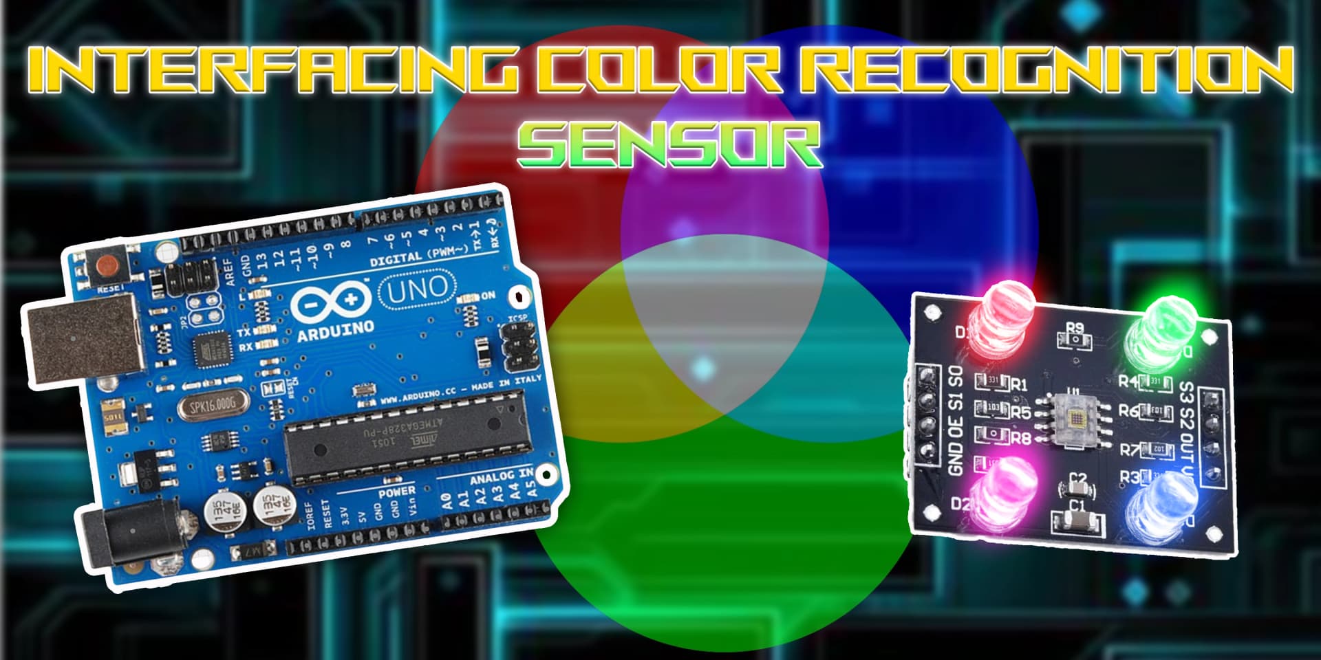
Interfacing Color Recognition Sensor with Arduino

Color Recognition Sensor
A Color Recognition Sensor detects and identifies colors in its surroundings. It is commonly used in industrial automation, robotics, and quality control applications where color differentiation is essential.
Working Principle of Color Recognition Sensor
The Color Recognition Sensor works by emitting light (usually RGB LEDs) onto an object and measuring the reflected light intensity. The sensor then processes this data to determine the object's color based on predefined thresholds.
Experiment of Code
A Color Recognition Sensor determines an object's color by analyzing the intensity of reflected light when illuminated with different colors. The Arduino reads the sensor's output and converts it into usable color data.
Wiring the Color Recognition Sensor to Arduino
To connect the Color Recognition Sensor to Arduino, connect the VCC and GND to +5V and GND. The S0 and S1 pins set the output frequency, S2 and S3 select the color filter, and the OUT pin connects to a digital input pin for reading color data.
Types of Color Recognition Sensors
RGB Color Sensor
- Emits red, green, and blue light onto an object.
- Measures the intensity of reflected light for each color.
- Processes the values to determine the object's color.
Infrared-based Color Sensor
- Emits infrared light onto an object.
- Measures how much light is absorbed or reflected.
- Determines the object's color based on absorption levels.
Pin Configuration of Color Recognition Sensor
Color Sensor Module
- VCC: Connect to +5V on Arduino.
- GND: Connect to GND on Arduino.
- S0, S1: Used for scaling output frequency.
- S2, S3: Select color filter (Red, Green, Blue).
- OUT: Outputs the frequency corresponding to the detected color.
Algorithm
Initialize Components
- Connect the VCC and GND pins of the Color Sensor to +5V and GND on the Arduino.
- Connect the S0, S1, S2, S3, and OUT pins as required.
Write the Code
- Set the sensor pins as INPUT and OUTPUT in the setup() function.
- Read the frequency values for red, green, and blue in the loop() function.
- Convert the readings into RGB values to determine the detected color.
Display Values or Control Devices
- Print the detected color values to the serial monitor.
- Use the readings to trigger specific actions based on color detection.
Test the Project
- Upload the code to the Arduino.
- Place objects of different colors in front of the sensor and observe the detected values.
Arduino Code
1// Pin configuration
2const int s0 = 4;
3const int s1 = 5;
4const int s2 = 6;
5const int s3 = 7;
6const int sensorOut = 8;
7
8int redFrequency = 0;
9int greenFrequency = 0;
10int blueFrequency = 0;
11
12void setup() {
13  // Set pin modes
14  pinMode(s0, OUTPUT);
15  pinMode(s1, OUTPUT);
16  pinMode(s2, OUTPUT);
17  pinMode(s3, OUTPUT);
18  pinMode(sensorOut, INPUT);
19
20  // Set frequency scaling to 20% (recommended)
21  digitalWrite(s0, HIGH);
22  digitalWrite(s1, LOW);
23
24  Serial.begin(9600);
25}
26
27void loop() {
28  // RED detection
29  digitalWrite(s2, LOW);
30  digitalWrite(s3, LOW);
31  redFrequency = pulseIn(sensorOut, LOW);
32
33  // GREEN detection
34  digitalWrite(s2, HIGH);
35  digitalWrite(s3, HIGH);
36  greenFrequency = pulseIn(sensorOut, LOW);
37
38  // BLUE detection
39  digitalWrite(s2, LOW);
40  digitalWrite(s3, HIGH);
41  blueFrequency = pulseIn(sensorOut, LOW);
42
43  Serial.print("R = ");
44  Serial.print(redFrequency);
45  Serial.print(" | G = ");
46  Serial.print(greenFrequency);
47  Serial.print(" | B = ");
48  Serial.println(blueFrequency);
49
50  // Simple color identification (can be calibrated further)
51  if (redFrequency < greenFrequency && redFrequency < blueFrequency) {
52    Serial.println("Detected Color: RED");
53  } else if (greenFrequency < redFrequency && greenFrequency < blueFrequency) {
54    Serial.println("Detected Color: GREEN");
55  } else if (blueFrequency < redFrequency && blueFrequency < greenFrequency) {
56    Serial.println("Detected Color: BLUE");
57  } else {
58    Serial.println("Detected Color: UNKNOWN");
59  }
60
61  delay(1000);
62}
63
Applications
- Industrial color sorting
- Automated quality control
- Line tracking robots
- Color-based object detection
- Smart agriculture sorting systems
- Consumer electronics and gaming
Conclusion
Interfacing a Color Recognition Sensor with Arduino allows accurate color detection for various applications, including automation, robotics, and sorting systems. With simple wiring and coding, you can easily integrate color recognition into your projects.